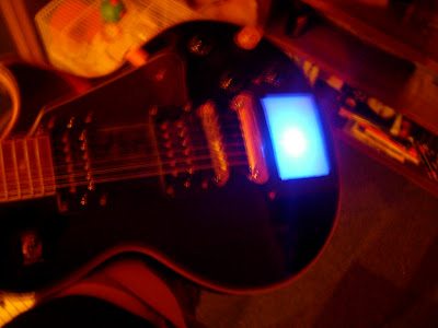
I post this now I've actually fixed it, but believe me when the problem occured I just thought over all the work I'd done and wanted to cry! (except in context it wasn't exactly that much work).. I couldn't wait around for the male to male DB9 cable to come next week from eBay(nowhere bothers with serial anymore, apparently) so I just hooked single wires into the corresponding pin holes on the 2 connectors, which were occupied.
When i connected it up, switched it on, touched the pad, and great, a light comes on to show I'm touching the pad, as usual. Then I realised move my finger as i might, the co-ordinates stayed at 1,1. Big problem. Big big problem.
I paniced, checked things, gave up temperarily, then got in touch with Phil to beg for some help. His great help encouraged me to carry on testing bits (although I got no multimeter) and stuff.
When I took the pad out the guitar, i looked at the DB9 wiring.
God knows what I was doing when I wired up the 2nd connector (serial port on the pad / guitar side of the pair) but, half the pins led to nowhere, and the two top ones were swapped I think. Maybe it spun upside down while soldering, either way, it was all messed up. I'd originally drafted my notes about what leads to what based on some letter labels I gave things. This seems to be a fucking shite way to do it that caused me more panick and stress, unless you're confident it makes sense, but still its flawed and I much preferred the idea of doing it the way that I fixed it...
There were already different coloured wires I'd soldered earlier leading from the ribbon connector pins, which needed desoldering from the DB9 wrong positions then re-doing.
The complicated and confusing bit...
I started by holding the connector + its wires flat down above the KP-1, until it was at the same angle it started (with the KP-1 on the floor in front, facing my way as if i was using it, it would fit pins down with the ribbon slot pointing to the void in the PCB, or towards you.
Then, I checked the colour of each wire coming from the connector. After checking one, say the 'top right' when looking from that same original angle explained above (to make the left right issue more foolproof) I referred to the wire coming from the PCB location previously occupied by that hole, in this position, this is the 'top right' hole. from there, I just made a list (these could be wrong, just to explain) showing which wires 'matched up' between the two seperated parts:
Yellow > Brown
Black > Red
Green > Grey
Blue > White
From here, all that needed to be done, was look for the pin which the Yellow wire occupied on the PCB's serial connector, lets say pin 1, or the pin hole at the top right when face on, and hook the wire up to the same pin solder pot on the back, I matched these up by keeping an eye on the way up the thing was (its a parallelogram, so just choose which way up to hold it and check it stays like that) then following the pin hole to the solder pot on the back. Obvious, just make sure you concentrate because I clearly didn't for a good hour the last attempt I tried.
If you have your cable, and have done that, just hook it up and give it a blast.
If you haven't, you can test it the way I did by getting some wires and just linking the individual pin holes on each DB9 connector which are in use by your circuit. That's 4, make sure they correspond.
If you've made a mess of it, you can still test the electronics, just link the right colour to the right colour, as explained above, just with a wire from the right pin hole to the other corresponding one, maybe that makes no sense.. But it's probably better to sort out the wiring anyway.
Good luck if you try it.
Welcome
This blog documents the production of my Kaoss Pad 1 Guitar Modification. The posts appear newest to oldest, so it may be easier to go bottom to top if using it as a guide or reading the whole thing, or just go off the archive navigation below.
Cheers for stopping by, hope its in some way interesting, please feel free to comment!
Cheers for stopping by, hope its in some way interesting, please feel free to comment!
Subscribe to:
Post Comments (Atom)

19 comments:
Post a Comment