I thought I'd just post to say thanks to the people who keep on linking this, I've had people say some great things to me regarding this blog and the work I did, even just a link titled 'amazing' really was a great thing to see, made me feel like I knew what I was doing or something.
Currently, I have a Ep Les Paul with a giant square hole in the bottom, and no patience left with KP1's... But I still would like to try and finish it one day.
But anyway, keep up the enthusiasm for this mod. In a lot of ways I now see running a guitar through a KP1, especially a good guitar, is a bit of a sacrilegious activity, given the quality, or lack of, on cheap Korg DJ FX units.
But its still pretty timeless and looks cool as fuck.
So keep coming, keep modding and keep dropping me messages, it gives me that little bit more of a reason to feel it was worthwhile getting up that day!
Cheers everybody.x
Sunday, 28 November 2010
Wednesday, 11 July 2007
R.I.P. Adam's KP Mod!
Well. In its final moments, i'm sure the program 30 tape delay almost said to me "oww", just before my toe, or possibly most my foot, shattered the KP's integral layers of the XY Pad, essentially rendering this a little bit crazier than a korg 505, offering the limited hold presets i'd saved for each setting, and makes a nice shit pre-amp.
SO.
THE KP XY CONTROLLER CANNOT BE FOOT OPERATED, NOT EVEN YOUR TOE. TRUST ME. IT REALLY CANT!
Signin' out!
Much love fellow crazy dudes
xx
SO.
THE KP XY CONTROLLER CANNOT BE FOOT OPERATED, NOT EVEN YOUR TOE. TRUST ME. IT REALLY CANT!
Signin' out!
Much love fellow crazy dudes
xx
Saturday, 31 March 2007
Rackmounted Kaoss Pad
 There it is, top left. It's not just sat there, tis mounted on to a BOSS RAD-50. It actually fits nicely, just short of half-rack width, but I kept it on top not only cos all the controls are on the top , but as i think its a cm or two bigger than 1U height. Either way, good place to keep it.
 Excuse the lights, i need a neon bar or something but, had them handy and cut down the cable so it was 40 ft long or something.
So in the shot is:
- The Modded Guitar
- KP-1 Rack top left
- BOSS RCE-10 Rack Top Right
- Digitech DSP-16 Rack centre
- Ibanez SM7 (sucks but sorta good)
- BOSS PS-3
BOSS OC-2.
I mounted it by putting ink on the centre hole on the Rack Adapter, designed to fit a BOSS micro unit really... its got a slight bevel designed to slot the boss rack unit into place better, but the KP-1's rubber feet bring the whole thing just above that, so its not balanced on a daft bump. Once the Ink had marked the point on the KP base that needed a hole for screwing in... I unscrewed the base, couldn't be chewed with going and getting a drill, so I just got a nail and a hammer an punched a hole in. Took some bending around to size, and left a big loada spikey material that I think could have contacted with the circuitry inside the KP when i put it back, so I filed this down.
Then i checked the screw I was using wouldn't be so long that i'd screw through the KP circuit board, just fed a nail down until it stopped and noted the distance, found a screw that was slightly too large and just worked it into the hole. End result, the KP probably more secure than the Boss Unit alongside it.
There's no harm in having it loose on a shelf on top obviously, but my rack is angled so it may slip off, and I like stuff mounted.
-adam
Monday, 19 March 2007
blue peter styley extra supplies
Heres the blue peter side of things, the idea being you should get some idea of how feasable your own ideas are, or how to do this without any extra bits and pieces:
Guitar Woodwork
Small Disposable stanley blade / scalpel / knife to cut plastic shell neatly
Flatbladed Screwdriver - the wannabe chisel
Hammer - Just to get the 'chisel' into the first bits of the wood, after that didnt really use it much
Guitar Touchpad Finishing
Black Video Case - Cut a square, made adjusments, made a hole, screwed it on.. an it did the job.
Long headed drawing pins - Great for temperarily fixing anything that would usually need screws to mount (PCB, DB9 connector, even the cover I guess but I had screws handy).
Black Felt Tip - Given the state of me guitar, a decent way to cover the odd scratches
Electronics
Solder - YOU NEED THIN SOLDER for the PCB mods - Really, unless youre really good, I used probably the thinnest I could imagine you can get it on a wire with (by hand anyway). For the LED circuit, i just fished up big dollops of this fat stuff and dumped it on. Not very professional but hey.
Cardboard - PCB's are a bitch to make properly, and really unneccesary for a few LED's. It'd probably work just as well without any sorta board, just loose components secured down somehow, but I prefer the card PCB, tis also handy for writing on the card your circuit diagram so its not confusing.
Elastic Bands - These were handy for securing stuff down that couldn't be easily mounted. Electric tape did little since its all hacked wood, so I just double looped the bands tightly, and pinned either end down with the pins. Like the battery, or wiring.
Some sandpaper helped, along with various implementations of electric insulation tape.
It depends what you're going for. Personally, I think the KP Body benefits from looking throwntogether and cut down. I mean, a window showing the divine korg circuitry, nicely lit looks pretty good, then with a clearly homemade computer serial port shoved on looks pretty neat no matter how dossed together it is.
Lesson calls, cya.
Friday, 16 March 2007
Job Done! well nearly..
Jesus. A few glitches, but I think although I cant really get the full effect without a cable and neatening off woodwork and stuff, but as far as the problematic bit, IE: doing the electronics without blowing anything or just, being unable to do it, transferring the pad without breaking it or the ribbon, making it all fit without destroying 99% of the guitar, creating a suitable cover (well, sorta suitable, it'll do!)... you get the idea.
Thats all Done!!!!!!!
Electronics in, honesty.. I never thought would work. Every time I checked it and turned it on, especially when I tried to check it with the pad somehow connected, I was almost sure it would just not work. I still am sure it will break like, but thats different.
I finished it. I have a Kaoss Pad, which has a 9 pin serial connector in place of the ribbon screen connector, and works just as well as it did before I changed anything, all LED's and buttons, effects and everything work perfectly still, as checked an hour ago.
I have a touch pad from the KP-1, seperated, in the same condition it was previously, with a connector on leading to another serial connector that will by cable simulate the original much shorter ribbon connector that previously linked to two up.
I have a guitar with a hole in it suitable for the touch pad component of the now two-piece device to fit in and be covered, and a good idea of how to do this again, much better, on a new guitar.
So I guess to all intensive purposed, the project was successful.
I would love to know about using 12V power from the pad still, and also to get a hole button on the guitar. I wouldn't mind copying Phil one more time and built a pedal board like he did. And hell experiment with god knows what else.
What i mean is, the project isn't finished, I'd not say. Besides, I still have to finish it off anyway so expect plenty more blogging on this for a while, then theres the other things listed above, plus the process of transferring the mod to another brand new guitar, hopefully using a much more sensible and guitar-considerate method of removing wood. And keep all flatbladed screwdrivers far far away to avoid temptation.
I'd also like to mention my guitar..
Its utter shite at present. It has a grounding / earthing issue, apparently, which is caused a really prominent humm / buzz that pretty much renders it useless, as the sound of the strings is barely listenable over the noise, sometimes. However, thanks to my E-Bow, which to be honest is way better for the KP-1 than standard picking, I can boost the signal that enters the humbuckers loads so that the noise cannot be heard...
The E-bows great for mixing with the delays and stuff so I'll be able to get some samples.
But what I'm trying to say mainly is that unless I control with my guitar and play with a working one, the sound from my own WILL suck. Lots of hiss and whining on some settings of the pad due to the noise input, and just generally the quality is going to be low, crap strings, virtually no bloody wood left in the guitar anyway, and:
Both humbuckers are now loose and unfixed, no screws.
The neck bends loads in normal playing causing pitch bends to occur on bar chords
The electronics are screwed anyway, regardless oft he earthing problem.
So just remember, the pad works the same as it did before. It's digital, its a microcomputer, so the tendancy is it'll either work, everything will work, or it wont.. effects wise CERTAINLY, so any rubbish sound quality on any samples I may record at any point, well, its not the KP or the Mod, just the shite zombie of a guitar.
So keep watching, I made this sound quite final but like I say I've only just started!
Just wanted to show off that the only bit I thought wouldn't work is now done, working.
Proof of concept, proved, as Phil said.
So thanks very much to Phil, both for his own site and his active ongoing communication and help, and to the people who leave the comments and use the site, its great doing something with a bit of an audience (except for when I thought it had completely failed!).
Cheers people!
-adam
Touch Pad connections + Another Big Problem
I post this now I've actually fixed it, but believe me when the problem occured I just thought over all the work I'd done and wanted to cry! (except in context it wasn't exactly that much work).. I couldn't wait around for the male to male DB9 cable to come next week from eBay(nowhere bothers with serial anymore, apparently) so I just hooked single wires into the corresponding pin holes on the 2 connectors, which were occupied.
When i connected it up, switched it on, touched the pad, and great, a light comes on to show I'm touching the pad, as usual. Then I realised move my finger as i might, the co-ordinates stayed at 1,1. Big problem. Big big problem.
I paniced, checked things, gave up temperarily, then got in touch with Phil to beg for some help. His great help encouraged me to carry on testing bits (although I got no multimeter) and stuff.
When I took the pad out the guitar, i looked at the DB9 wiring.
God knows what I was doing when I wired up the 2nd connector (serial port on the pad / guitar side of the pair) but, half the pins led to nowhere, and the two top ones were swapped I think. Maybe it spun upside down while soldering, either way, it was all messed up. I'd originally drafted my notes about what leads to what based on some letter labels I gave things. This seems to be a fucking shite way to do it that caused me more panick and stress, unless you're confident it makes sense, but still its flawed and I much preferred the idea of doing it the way that I fixed it...
There were already different coloured wires I'd soldered earlier leading from the ribbon connector pins, which needed desoldering from the DB9 wrong positions then re-doing.
The complicated and confusing bit...
I started by holding the connector + its wires flat down above the KP-1, until it was at the same angle it started (with the KP-1 on the floor in front, facing my way as if i was using it, it would fit pins down with the ribbon slot pointing to the void in the PCB, or towards you.
Then, I checked the colour of each wire coming from the connector. After checking one, say the 'top right' when looking from that same original angle explained above (to make the left right issue more foolproof) I referred to the wire coming from the PCB location previously occupied by that hole, in this position, this is the 'top right' hole. from there, I just made a list (these could be wrong, just to explain) showing which wires 'matched up' between the two seperated parts:
Yellow > Brown
Black > Red
Green > Grey
Blue > White
From here, all that needed to be done, was look for the pin which the Yellow wire occupied on the PCB's serial connector, lets say pin 1, or the pin hole at the top right when face on, and hook the wire up to the same pin solder pot on the back, I matched these up by keeping an eye on the way up the thing was (its a parallelogram, so just choose which way up to hold it and check it stays like that) then following the pin hole to the solder pot on the back. Obvious, just make sure you concentrate because I clearly didn't for a good hour the last attempt I tried.
If you have your cable, and have done that, just hook it up and give it a blast.
If you haven't, you can test it the way I did by getting some wires and just linking the individual pin holes on each DB9 connector which are in use by your circuit. That's 4, make sure they correspond.
If you've made a mess of it, you can still test the electronics, just link the right colour to the right colour, as explained above, just with a wire from the right pin hole to the other corresponding one, maybe that makes no sense.. But it's probably better to sort out the wiring anyway.
Good luck if you try it.
Thursday, 15 March 2007
KP-1 Body & PCB Dismantling Guide
Please bear in mind, these pictures were taken with the touch pad not there. All thats different is there should be a white ribbon, but its explained without anyway!

Firstly, there are 4 main exterior screws fixing the back panel onto the body. This seems the obvious place to start, however it probably makes more sense to begin with the step in the photo below (I just found it less awkward tipping it on its side to with the back cover ON where if it fell the circuit wasnt exposed to bits an pieces, but its a minor risk and up to you.) So just unscrew these 4 and lift the back panel off carefully by its rubber feet or let it drop upside down, then marvel Korg's glistenin ocean of silicone and solder. Pretty neat. Be careful from now on.
 These 5 screws hold the upper PCB onto the back on the device. You'll see next that this is because on the interior, the PCB is only held on by 2 opposite screws, so I guess its to stop the inputs and outputs etc having to support that edge. But for now, it wont make any difference pulling all these out first, I found it easier than starting with the back panel.
Bear in mind how annoying the ones in the middle of the RCA connectors are until you get the nack.
Now you're onto unscrewing the actual PCB. The first one is on the top, makes sense, and assuming you just completed removing the 5 screws on the back of the exterior, all you need now do is remove the 2 screws marked yellow. Once you've done this, DONT try to lift the PCB at any sort of angle. Theres loads of stuff really compacted and will clash and simply not come out UNLESS you just carefully slide it in (so the inputs etc come into the device) keeping it flat, it will not go any further than literally about exactly where it needs to be, then once its just there, lift it up keeping it horizontal. Once its loose (although remember it's still connected by plenty of ribbons and wires to the lower PCB and another small one) you can lift it over the other, and I just proped it up at an angle over the edge near the ribbon cables.  OK.
OK.
Now you're looking at the lower PCB. To remove the touch pad, unscrew the 5 yellow circled screws on the pad. My ones kept falling around the PCB which probably isnt very good at all, so I remembered to grab them after a while.
Circled RED are the ribbon connectors terminals (the component is on opposite side of PCB). Normally, a thin green semi-transparent 4 way ribbon connector slips into the connector on the opposite side, so be careful when you move the PCB around because its pretty fragile, or seems it anyway.
This is a close up of the terminals. The colours don't, really show anything I'm not entirely sure why I put them on in different colours. Make sure you have a good knowledge of what was where, I just remembered how it all fit together and worked it out logically and visually, after writing it down caused some problems!
The ribbon connector end has one side which has bare terminals visible (without plastic over). The ribbon fits in the connector such that those terminals face from the pins on the connector. On the KP-1 at least.
Much of a nasty job as it was, I made a scrappy as hell job of both desoldering and soldering all of this stuff, melted a lot of plastic :D and, well, I'm surprised it all worked okay.
What WAS tricky was desoldering the ribbon connector. I didn't wanna apply too much heat, so i applied pin prick soldering iron (but it was 30w, not recommended lower ones) touches to each terminal, but that was almost useless,the action of the solder sucker wasn't an awful lot of help as it shook everythin, a lot...
So i in the end risked frying the PCB and just held the iron at an angle, so that at least 2 pins solder was molten at once, meaning you could actually prise it out tiny pieces at a time.
This part can actually be done without unscrewing the bottom board I realized, working with your hands through the missing pad gap.

This is the PCB when I'd put it back together and added 4 wires to the holes which the connector terminals used to occupy. At this point, I just kept the connector attatched to the ribbon seperate, as this is where it will be eventually, with the DB9 Serial Port on. Likewise, these wires were put to use as seen below...

This is the PCB when I'd put it back together and added 4 wires to the holes which the connector terminals used to occupy. At this point, I just kept the connector attatched to the ribbon seperate, as this is where it will be eventually, with the DB9 Serial Port on. Likewise, these wires were put to use as seen below...
The wires were soldered on using the 30W solderin iron, and this 'ultra-fine diametre solder for SM components', which disappeared to nothing sorta! But really suited this bit cos the last thing you need is a flood of solder shorting the 4 pins out or something. So this thin solder served me well during the job.

There, not very neat and tidy, and probably prone to snapping, but theres the basic electronics modification complete. For the PCB at least, the pad process is seperate (haven't got photos at present and I treat it as a seperate process in a way).

There, not very neat and tidy, and probably prone to snapping, but theres the basic electronics modification complete. For the PCB at least, the pad process is seperate (haven't got photos at present and I treat it as a seperate process in a way).
I intend to add a plastic screen to replace the missing pad, and go for Phil's mounting the serial connector onto that.
I kept trying the pad in the guitar, then when it wasn't mounted in there I just put it in a folded static proof bag, and a bubble wrap envelope, just cos they were both handy and seemed like a good plan.
And thats pretty much it, there'll be a seperate entry on sorting out the Pad's electronics, although its pretty much self explanatory. That one explains about linking it up correctly, partly cos theres a few things I wanna double check, and in theory you can have the wires in any pin you like for now as long as you match it up right in the next part.
Hope thats helpful, feel free to comment.
-adam
Tuesday, 13 March 2007
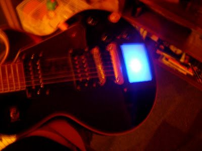
LED Circuit Working


So these are those ultra bright LED's I got off eBay. The resistors were for 12V so maybe that's reducing the brightness, but I'm using them anyway.
Again, I had no PCB material, well, proper PCB material. Some dense corrigated card did the job, pin holes punched in. Solder applied at the back although it in no way bonds with the material.
I put it together with the guitar and pad, to get the general effect, posted photos above.
PS: I fixed the nut, sorta... I think theres still a slight hole for the bottom bit to catch into, like its original hole carries on after the gap. I just took the nut off, pulled them out, put it in an placed some padding foam in with it so its secure and grips better. For the moment, its straight, strung up okay, and isn't giving me any problems yet.
Most electrics equiptment should come tommorow.
Problem #1 - Bugger.
My Poor Tailpiece
Well, I had a feeling this might happen, and it did. It probably wouldn't if only the guitar was more than 30% wood but, all it is is the two screws + fixings that hold the actual stoptail tailpiece at base of strings in, aren't fixed anymore.
Please bear in mind that I doubt this would ever happen (with my measurements and positioning) if the guitar was solid body and better quality hardwood (such as the Epiphone range, which I believe tend to be cheap yet great bodies).
The cause is probably a mix of careless crap you can easily learn from:
Still, its fine at the minute. Its just a prototype. But in fear of a metal tailpiece and 6 slicey thin strings wrapping round my wrist at 20mph, I might avoid playing it for now.
Again, I probably could have been much more consise about that one.
Me guitars fucked cos I wasn't careful.
-adam
Well, I had a feeling this might happen, and it did. It probably wouldn't if only the guitar was more than 30% wood but, all it is is the two screws + fixings that hold the actual stoptail tailpiece at base of strings in, aren't fixed anymore.
Please bear in mind that I doubt this would ever happen (with my measurements and positioning) if the guitar was solid body and better quality hardwood (such as the Epiphone range, which I believe tend to be cheap yet great bodies).
The cause is probably a mix of careless crap you can easily learn from:
- Firstly, odd chunks of wood coming out in layers and chunks from above the hole, under the painwork, near the tailpiece. The worst affected one has a 8mm deep tiny hollow allowing me to see the body of the nut inside its messed up position.
- Also, the width of my hole pretty much covers the width (unintentionally) of the main interior wooden body strip following the neck's direction inside. This could have led to stray pieces of wood as I could have almost completely sliced the 'plank' width ways.
- All of this probably meant that when it came to belting my guitar with a screwdriver and hammer, this just slowly dislodged it and loosened it, allowing it do physically wreck its original bored holes, and if it gets to more of angle than its at currently, the tension from the strings will probably just pull it out.
Still, its fine at the minute. Its just a prototype. But in fear of a metal tailpiece and 6 slicey thin strings wrapping round my wrist at 20mph, I might avoid playing it for now.
Again, I probably could have been much more consise about that one.
Me guitars fucked cos I wasn't careful.
-adam
Materials Used / Purchased
I'll try to be specific, any eBay links may well have changed or be dead. I didnt include the guitar.
Korg Kaoss Pad 1 (KP-1)
I didn't buy this for this project, the guitar mod idea came after, but still neccesary. A kp-2 would do, as Phil @ unmaintained shows well, but a KP-1 is cheaper, simpler circuit (i believe, although it doesn't make that much difference) and what I had to use.
This cost me £60 including a tenner p&p from an eBay seller that I struck a deal off the record with ;)
CLICK HERE TO SEE AN eBay SEARCH (will include, most likely, various models)
2 x 'DB9 Socket' (Generic 9 Pin Serial Female Connectors)
I had real trouble finding these things. Moved away from eBay. Found an online electronics store based in the UK that sells them, just under a wierd heading. They call them DB9 series which makes sense, and they refer to female as socket, as apposed to plug. Follow this link to find them:
SOCKET: http://www.cavuk.com/product.php?productid=110&cat=0&page=1
PLUG: http://www.cavuk.com/product.php?productid=109&cat=10&bestseller
These 2 came to about £3.50 or £4 including postage.
Solder Sucker (solder remover, desoldering)
I remembered these from secondary school, spring loaded vacuum style sucker that retrieve molten solder while you're desoldering. I was going to attempt without but most guides on the net involved the solder sucker without question so I thought I best buy one off ebay.
Total Price (including p&p): £2.99
5 x Mega-Bright Blue 5mm LED's (15000mcd)
Thought they'd be handy with the screen, and the seller i link below is excellent. He provided quality advice on wiring the components and all round great salesmanship.So buy off him! Includes free resistors to but I bought some 1K's anyway, which are too high for this. (12V would be more suited but Im using 9V bateries).
Sale including postage: £2.74
http://search.ebay.co.uk/_W0QQfgtpZ1QQfrppZ25QQsassZteltronic123QQssPageNameZSTRKQ3aMEWNQ3aMESOI
Solder Wire - Fine Diametre for SM Components
Got some thicker stuff anyway but incase theres anything really small probably a good idea to have some, cos my other stuff is really really thick.
Sale Price including postage: £1.49
30W Soldering Iron
Not sure how much I trust a 99p soldering iron but, ther was postage too if thats meant to make me feel better. eBay search on soldering iron is below.
Sale price (inc. postage): £3.98
http://search.ebay.co.uk/search/search.dll?from=R40&satitle=soldering+iron
Photographs, Measurements, Annotations
Here are some photos I took covering various parts of the project so far.


These are general shots showing the scale and position of the hole I dug. As you can probably tell, quality fell below the need to just get the concept working, so yes, its pretty scrappy.
The guitar, by the way, is obviously a Les Paul Copy, called Starfire by Tanglewood. Its about 6 years old (since bought). An yeah, isn't me bedcovering mint.

This warped a bit on upload. The light blue marker shows the gap I carved for the ribbon (so it wasnt folded against the wooden housing). But it should be at the bottom really!
The Red marker shows the hole to allow for access to the guitars normal electrics wiring, where my 9V battery will be stored.
The green marker shows (badly) the hole that leads to where the female serial connector port will be mounted.
The hole itself measures, around about 10x12.5cm.

These are shots of the stripped down Kaoss Pad. All that is missing is the touch pad. The red marker shows the ribbon connector, which will later be removed and rewired at each end to allow for the serial connection instead.
 instead.
As phil helpfully said, you remove this by gripping the side edges of the WHITE CONNECTOR (not cable) and slide it down, its a bit tight but it does go. Slide it away from the PCB, and then once its moved as much as it naturally will, the ribbon will pop out will next to no effort at all.


And finally, I checked that it still works as it is at current, and it does. Which is good after a few clumsy mistakes when removing PCB's. I ran sound through, used the hold settings to gain effects which did work.
I also reconnected the pad to check it still worked after having been moved around a lot and possibly damaged during this. It still worked, then centre light that signifies touchpad input / activity worked as should.
Ideal!
Monday, 12 March 2007
We (I) begin...
There ain't much time span to this project, so far at least. The motivation was a considerable mixture of Matt Belamy's similar adaptation, and also some realistic motivation (made me half convinced it could possibly work for me) from Phil, although I must say he seems much more experienced in the field.
I hope somebody looks at this and instantly stops wondering, picks up the sharpest thing they see, cut a hole in their guitar, then theres some motivation to make it neater and stick a snazzy kaoss pad mod there to cover your destructive acts. I also hope it works for them, and for me. Time will tell.
The spark...
So me and my mate JP are sat pretty cabbaged in my dull room having sat there all day not all that with it, and i think boredom alone triggered it. As well as some heavy drooling over internet resources such as Phil's youtube features that is. It suddenly seemed remotely possible and like a good idea.
Start hacking...
So this was a slightly poor order to do things. But I thought i'd at least see what sorta wood I was dealing with. I did this willingly because my guitar is on its last legs, needs a complete rewire, has a grounding problem, dodgey neck, unfixed humbuckers with lost screws and springs and can be deemed no better than my first guitar that served me well and had fun from my side, but a piece of 6 year old 120 quid new shit to the majority of the western world.
What i'm trying to say is should you be staring across your room with an evil grin at your new Gibson LP or, anythin that doesnt stoop as low as my previous description, you may want to pause for breath and really think. Especially about the method of removing the wood you use, compared to mine that is!
With a screwdriver...
Parents were away, no toolboxes seemed to be on the property which wasn't good, but there was indeed a dodgey flatbladed screwdriver, a threaded crosspoint, a hammer, a rather useless and awkward inappropriate yet eventually sorta handy file, and as you'll see later, some PVA glue too (you'll see later).
I would of used a chisel, but none were anywhere. So the flatblade screwdriver had to do, and all in all it did a rather good job. Only because (i think) though, my guitar seemed to be made of really really soft wood. ply, i think, but it was even crapped, more like shavings compacted together, i forgot the name (mdf) but not really, argh. it was annoying. Then i realised it only has wood up the strip following the neck, hollow edges.
First however, i used a stanley knife (with a plastic handle) to mark vaguely (careful, this really scratched the fuck out of my guitar, i got over it quick, you may not) the boundaries straight off... the aim being that when the paint / plasticy stuff fractured off, it didnt take half the body's worth with it, just that square.
And then I hacked. Mostly just piled it in with a hammer half way and came back on myself to pull chunks, then just hacked in, twisted to get a bit under the surface and just, worked little chunks out to get it square. I didnt make it go through the back, saw no need for that.
My LED is going to have to be powered by battery cos I don't want to try to do anything complex getting power of the KP if its possible anyway, so I'm just going to put some temp mounts for a battery in the electronics access of the guitar.
The hole for the pad overlaps handily on my guitar with the electronics access on the back, meaning an ideal place for the battery clip to fit through for power.
The output for the KP Pad will be next to my jack output. Here, I marked another strip, estimating how large a serial connector would be, cut it with the blade, hacked off the paint neatly (sorta), then started to hack into that in the same way. I think I just alternated between which side I was caving the hole through and eventually got there, widened it a bit and left it at that.
I then finished by maximising the depth of the pad hole, leaving the upper walls as they were as it supported the pad well at a good level while i cant mount it properly. This could be damaging to the KP Pad im not sure. The deeper part was to allow space for the electronics (LEDs) I plan to add behind the screen.
PVA Glue.. thats stayed fluid for like. 7 years or something!
This idea came into my head just because it was worrying me how much dust and shavings would be floating about (especially when in motion) near the KP Touchpad with a freshly hacked softwood body there. Probably with good cause.
Although this still worries me, probably with good cause, I think I made it slightly better by applying a moderate layer of PVA glue across the reachable majority of the affected woodwork to contain any loose sawdust etc. It certainly looks a bit neater as well, almost like varnish. It a bit nastier to hack into on the surface after doing this thats why I did as much hacking as I think I'll have to before doing it (although I did do it 3 times before that!).
Makeshift pad cover / 'housing'
I say housing, but it doesn't house it too well. The pad actually rests where it happen to rest in the hole, usually a cm or so deep in the hole, it hasn't knocked about at all though, stays in place probably cos the woods so hacky and gives good friction to hold it still once its in place (but like i say, could be destroying the pad itself.
The housing I made was, argh. It was a video tape box. Black, sliced it down to get the flat front sheet of plastic, an then marked a basic square bigger than the hole, thats all i knew. From there I sliced it down a bit, however to screw on would need to clear the hole and span a cm or two onto the wooden guitar body so the screws fixed into somewhere. The guitar's adjustment knobs got in the way here, and I simply cut an arc out in the middle side for one, then another at the top for another, following that, it fit relatively neatly and evenly on the front.
I then hacked a medium sized hole (not full sized) in the middle of the cover, and kept putting it on top in position so I could visualize where the 'centre would be'.
I measured the edges of the void in the Kaoss Pad's front cover (its original pad cover) and made a paper square to scale, and just moved it about until it looked right, scraped a marker line then hacked through the cover to give the neatest square I could. This is generally cosmetic, although it would stop the pad being able to fall out the front, which happened the first time i tryed to mount it.
A better cover would support both sides (also helping to keep the layers together) and prevent dust getting in at all. I may just seal it off best I can with plastic or something underneath. God knows.
I just bore some holes with the scalpel, screwed direct into solid woodwork on the guitar and it all fit together nicely and in all honesty for the fact of how dossed and low or, none existant budget this is turning out to be, looks alright, and so I'm told also.
So thats the guitar preperation. Like I said, you may want to alter the order, work on the electronics first cos, in fairness you can do all of that before destroying a guitar. It just really didn't matter to me.
God that was a rant. I'll add images and measurements soon.
Introduction
Adam's KP-1 Softbody Budget Expertise-free Guitar Mod
Welcome!
This blog is basically intended, in its most basic sense, as a documentation of my current project.
I intend to mount the Kaoss Pad 1 (KP-1) touch pad xy controller to my guitar, and modify the electronics on both the touch screen and the seperated remainder of the device such that a serial port will connect them together when required.
It is based directly on the work of Phil's Kaoss Pad Mod (unmaintained.com) which was based on the Manson guitar I believe.
The Situation...
- I'm 19. Lack any previous experience of either guitar modifications or electronics.
- I'm on a budget. A real budget £15. I'm sure many people share this position.
- I don't really have any specialist equiptment, all soldering stuff and extras (except the KP and my guitar) came off ebay for about £15 in total, includin stuff for the LED's.
- This isn't a KP-2 like Phil used. It's a KP-1. Cheaper alternative, hopefully less complex. But good to have a reference to it working with the KP-1 cos much of this I had to guess.
- I plan to purchase all required extras off eBay. I'll try to add handy product item listings and search keywords cos this way quite time consuming for me to figure out myself!
- I couldn't find a chisel so I hacked my softbody Tanglewood Starfire LP Copy with a flatbladed screwdriver and a now blistered hand. IT CAN BE DONE! The guitar bit that is, at least.
So I'll post properly each time I can be bothered to document. I'm actually part way through at the minute (sepearted 2 parts and hacked guitar, made makeshift cover). So i'll probably be changing my tenses all the time and posting retrospectively to a point.
Cheers for visiting I hope its interesting, I'll try to add images and other stuff when I grab the time.
-adam
Subscribe to:
Posts (Atom)